Building an model of an epoxy thermoset material
Version: S-2021.06
In this tutorial you will learn how to build a model of a thermoset material created by cross-linking different molecules using the example of an epoxy-amine system. You will then learn how to analyze the cross-linking reaction to estimate the gel point of the material. Understanding the structure and properties of different thermoset materials is critical in choosing the correct material for a wide range of applications. It can also help in designing new materials with certain desired properties. This tutorial demonstrates how you can use the QuantumATK tools to simulate cross-linking reactions between different molecules. This methodology can be applied to a wide range of materials and chemical reactions.
To generate a model of the thermoset material, a combination of classical molecular dynamics and a cross-linking algorithm is used to create a trajectory of how the material may be formed through reaction. This results in giving a series of final structures at high degrees of cross-linking. The properties of these structures, such as glass transition temperature or Young’s modulus can then be further investigated using molecular dynamics. This tutorial focuses on building the initial model of the material. A further tutorial, Analyzing the thermo-mechanical properties of a polymer material demonstrates how to estimate the thermo-mechanical properties of the thermoset material using the model built in this tutorial.
Theory
Epoxy-Amine Materials
Polymer materials can be generally categorized as either thermoset or thermoplast materials. Thermoplast materials typically melt on heating, and are usually constructed of individual polymer chains that are bound together through non-bonding forces. Plastic materials such as PVC (polyvinyl chloride), PET (polyethylene terepthalate) and polyethylene are all types of thermoplast polymers. In constrast, thermoset materials typically do not melt on heating, and are constructed of a 3D covalently bonded network. This network can be formed through post-synthetic cross-linking of polymer chains or by using reactant monomers that are able to link more than two other monomers. Common thermoset materials include Bakelite, vulcanized rubbers and polyester resins.
Epoxy resins are one industrially important class of thermoset materials. These materials are commonly made of two components. The first is the resin containing epoxy functional groups. The second is a molecule containing functional groups that react with the epoxy to form a covalent network. This second molecule is often termed a hardener, and commonly contains amine functional groups. Primary amines and epoxy functional groups can react in a two-stage process requiring one amine and two epoxy groups. In the first step the amine nitrogen attaches to an epoxy carbon, opening the epoxy ring and transferring a hydrogen to the epoxy oxygen. This forms a secondary amine and alcohol functional groups. This secondary amine is able to react again with another epoxy group using the same mechanism, this time producing a tertiary amine. This reaction scheme is illustrated in the figure below.

Fig. 15 The reaction mechanism of epoxy-amine cross-linking.
Thermoset Building Algorithm
In order to build a representative model of a thermoset material, it is necessary to arrange the molecules in such a way so that the internal bonding energy is minimized and the resulting structure is in a relaxed configuration. Given the various constraints on each molecule this is very difficult to construct directly. A more productive approach is to start with a system of necessary reactants, and then progressively react and relax the structure so as to mimic the actual chemical process used to form the final structure. Variations of this type of building approach have been published and have shown to produce realistic models[1][2][3].
An overview of the building algorithm implemented in QuantumATK is shown in the figure below. The building process starts with an initial configuration of the system before cross-linking. The iterative building process starts with saving a snapshot of the current configuration. Available cross-linking reactions are then performed according to a reaction scheme specified as input to the calculation. As this chemically transforms the structure, new atom types and potential terms are automatically calculated for the new configuration. The system is then relaxed using NVT molecular dynamics. In this step reaction coordinates from the previous cross-linking reaction are gradually relaxed over the whole duration of the dynamics step. This ensures that additional strain is not added to the configuration by the rapid minimization of internal coordinates. Finally, an NPT molecular dynamics step is carried out to further relax the configuration and also correct the density of the overall system. This loop continues until the reaction is completed, producing a trajectory of structures along the path between initial and final cross-linked structures.

Fig. 16 The general algorithm used to build cross-linked structures.
In this simulation the reaction scheme used to transform the configuration can be specified in one
of two ways. The simplest way is to use a ReactionTemplate class. Here molecular
configurations are given that represent the reacting functional groups at different stages of the
reaction. These templates are then used to identify reacting groups in the input configuration by
scanning the bond graph. Some templates for common cross-linking reactions are also defined in the
CrosslinkBuilder script block. The second way reacting atoms can be specified is using a
CrosslinkReaction class. Here the reaction scheme, including bonds formed and broken, are
specified using tags which correspond to tags in the configuration. Using this method it is
possible to have complete control over which atoms react in each step. In this tutorial we will use
one of the pre-defined templates.
With the reactions defined, further rules are used to determine which atoms react at each step. Bond and angle limits are employed that specify that no reaction can take place if it creates bonds lengths longer than or bond angles more narrow that particular cutoffs. This ensures that distortions to the overall chemical structure are limited when reacting the configuration. It is also possible to limit the total number of reactions performed at each step. During the NVT relaxation step two different approaches to relaxing bonds are taken. For atoms that are only connected to the structure through a single extended bond, the position of these atoms is directly optimized before the NVT step begins. This is most commonly applied to hydrogens migrating from one atom to another. For newly formed bonds that connect two different substructures, these are relaxed gradually over NVT simulation. This is done by shifting the minimum in the bond potential for those atoms from the initial extended bond length to the final equilibrium bond length.
The final completion point of the reaction is determined by three criteria which, if any one is satisfied the reaction is determined to be complete and the building process is complete. The first criterion is that a specified extent of reaction is achieved. This allows cross-linking calculations to be stopped at any point along the building process. A second criteria is that no reactions are found during a set number of steps. As the building process is carried out it is possible to not find any possible reactions that conform to the bond and angle limits. If this happens after a set number of consecutive cycles, it can be assumed that there are no more viable reactions to be found and the building process is complete. The final criteria is when a specific bond cutoff is reached. During the reaction cycles it is possible to increase the reaction bond cutoff if no reactions are found during the cycle. This allows the building process to prioritize bonding molecules that are relatively close and only later include longer bond formation when necessary.
Building the thermoset model
Building the epoxy-amine configuration
To start building the epoxy-amine system, we first have to build epoxy and amine molecules. In this
tutorial the molecules diglycidyl ether of bisphenol F (EPON-862) and diethylenetoluenediamine
(DETDA) are used. The structures of each of these molecules are shown in the figure below. Open the
Builder  and select . Start by building
a molecule of DETDA. This can be done by switching to the molecular builder. Here atoms in the
existing configuration can be replaced by selecting atoms or chemical groups and clicking on
hydrogen atoms. New atoms can also be added by clicking and dragging from an existing atom. This
will add an atom bonded to the selected atom. Bonds can also be added to the configuration by
clicking and dragging between two atoms. For bonds to be created the option Static bonds needs to
selected. When Static bonds is enabled the displayed bonds are saved with the configuration. Once
a molecule of DETDA is created, add another configuration to the builder and create a molecule of
EPON-862. At this stage it is also convenient to set the appropriate forcefield tags for the
molecules. In this simulation the OPLS-AA forcefield is used. To calculate the forcefield types go
to the Forcefield Types plugin in the Selection Tools section. Select the
and select . Start by building
a molecule of DETDA. This can be done by switching to the molecular builder. Here atoms in the
existing configuration can be replaced by selecting atoms or chemical groups and clicking on
hydrogen atoms. New atoms can also be added by clicking and dragging from an existing atom. This
will add an atom bonded to the selected atom. Bonds can also be added to the configuration by
clicking and dragging between two atoms. For bonds to be created the option Static bonds needs to
selected. When Static bonds is enabled the displayed bonds are saved with the configuration. Once
a molecule of DETDA is created, add another configuration to the builder and create a molecule of
EPON-862. At this stage it is also convenient to set the appropriate forcefield tags for the
molecules. In this simulation the OPLS-AA forcefield is used. To calculate the forcefield types go
to the Forcefield Types plugin in the Selection Tools section. Select the OPLS-AA
forcefield and then click the Calculate Types button. This automatically assigns types based on
the elements and the bond graph of the configuration.
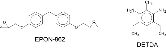
Fig. 17 The chemical structures of the initial reactants EPON-862 and DETDA.
Note
The molecular builder is a powerful tool that enables you to easily build a wide range of molecules. For a more detailed introduction to the many features, see the molecular builder tutorial video here.
To build the initial starting structure for the cross-linking reaction, these molecules need to be
packed into a simulation cell. This can be done using the Packmol builder plugin. Open the
plugin and add both molecules from the Stash into the molecules box. As both molecules have two
functional groups, and two epoxies are able to react with each amine group, a stoichiometric mixture
contains two epoxy molecules for every amine. In the Packmol plugin, set the amine count to
128 and the epoxy count to 256. Also set the Cell density to 0.6gram cm-3. The
Packmol input dialog is shown below. Clicking Create will now add the starting configuration
to the Stash.
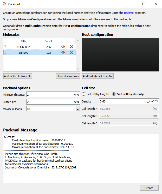
Fig. 18 The input options used in the Packmol plugin.
As Packmol provides only an approximate molecular packing, it is recommended to improve the
initial packing of the molecules by running an additional molecular dynamics calculation. To set up
this simulation, send the structure generated by Packmol to the Scripter
 using the Send To icon
  . First add a Forcefield
calculator block to the script. To select the forcefield, open the calculator block and in the
buttons on the right select New –> OPLS-AA. This adds an OPLS-AA potential builder to the
script that will construct an OPLS-AA forcefield for the starting configuration. All of the default
options for the potential are suitable, so just click OK on the resulting dialogs and return to
the script generator.
. First add a Forcefield
calculator block to the script. To select the forcefield, open the calculator block and in the
buttons on the right select New –> OPLS-AA. This adds an OPLS-AA potential builder to the
script that will construct an OPLS-AA forcefield for the starting configuration. All of the default
options for the potential are suitable, so just click OK on the resulting dialogs and return to
the script generator.
Next, the molecular dynamics simulation can be defined. Since both the velocities and density of
the structure need to be equilibrated, the Stable NPT template can be used. This defines three
different molecular dynamics methods that equilibrate first the velocities and then the densities
in a way that allows for high-energy or approximate starting structures. To add the template, in
the Template drop-down menu select Molecular Dynamics –> Forcefield –>
Stable NPT Equilibration. The default for this template equilibrates the structure to a
temperature of 300K. As the cross-linking is being done at 480K, the configuration should be
equilibrated to this higher temperature. Open the last molecular dynamics block and set the
Reservoir Temperature and Final Temperature to 480K.
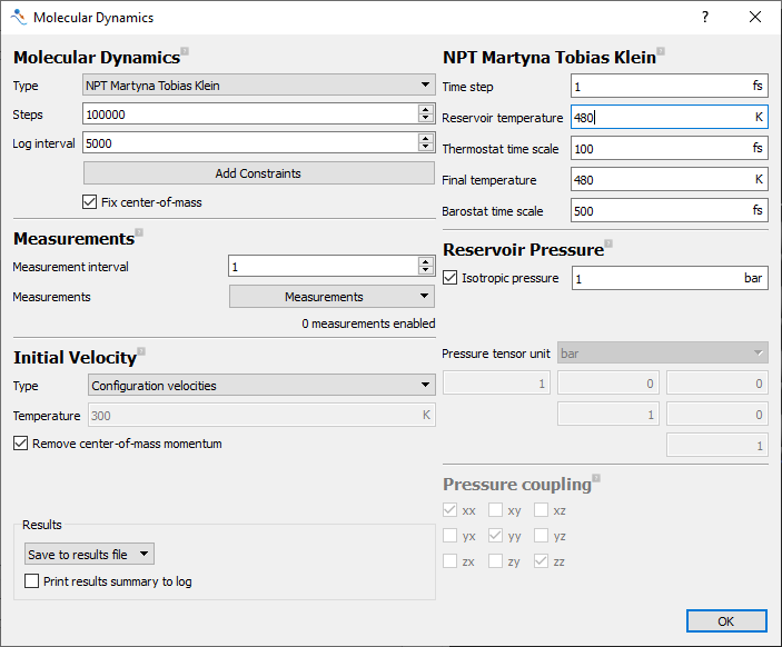
Fig. 19 The input options used in the initial molecular dynamics equilibration.
The final MolecularDynamics dialog is shown above.
With the OPLS-AA forcefield and the molecular dynamics defined the script is now ready to run.
Send the script to the Job Manager and run by using the icon . This will produce
three molecular dynamics trajectories equilibrating the initial structure. The final image in the
last trajectory will next be used as a starting configuration for the cross-linking simulation.
Building the Cross-linked Thermoset Material
Start by dragging the final image of the previous trajectory onto the Scripter
. This opens the configuration in the Scripter where the script for the
cross-linking simulation can be created. Set the output file to Epoxy_Amine_Thermoset.hdf5.
Next, add a CrosslinkBuilder block from the Optimization group. This is the block that
carries out the cross-linking simulation. The forcefield to be used is defined as part of this
block, so a calculator does not need to be added first.
Open the CrosslinkBuilder block to set the parameters for the reaction. Start by choosing a reaction scheme. This is done by pushing the Select start group button. This brings up a database of the available reaction templates. The reaction templates define both the atoms in the configuration that are able to react and the way in which the bonding changes during each reaction step. An animation of each reaction scheme is shown in the window below the list of reactions. In this system an epoxy is reacting with an aromatic amine, so select the Epoxy Aromatic Amine reaction and select Add. This adds this reaction template to the script.
Next the parameters for the reaction need to be set. In this dialog:
Select the Maximum number of reactions and set the value to
20. This limits the number of reactions per step to 20. This can prevent high-energy configurations freezing in during the initial steps of the reaction.Set Temperature to
480K. This is the temperature used in the MD relaxation steps.Set Bond search radii increment to
0.25Å.Set Maximum bond search radii to
10Å. These two options set how reactions are searched for. After each cycle, if no possible reactions are found, the bond search radii is increased by the set increment. When the bond search radii reaches the maximum value, the simulation is completed. In this way the bond search radii is used as a termination criteria. The options Finish after cycles without reaction and Reaction percentage can also be used as termination criteria for the simulation.
The final dialog box is shown in the figure below. The calculation is now ready to be run. Send the
script to the Job Manager and run by using the Send To icon . The script
produces a Trajectory containing a snapshot of the configuration after each NPT equilibration
following the reaction. This calculation may take several hours, as it typically goes through
around 100 reaction cycles before completion.
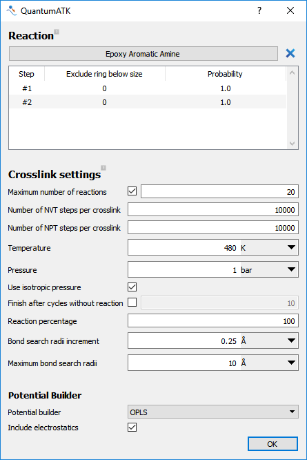
Fig. 20 The input options used in the CrosslinkBuilder.
Analyzing the Thermoset Reaction
Once the calculation has completed the cross-linking reaction can be examined. In this section the precise configuration produced by the simulation depends on the initial starting configuration and assigned molecular dynamics velocities, which are randomized. Each calculation will therefore produce similar, but non-identical final configurations. During the calculation information about the number of reactions performed, the density of the material and the stage of the simulation is written to the calculation log. An example of the expected output is shown below.:
+------------------------------------------------------------------------------+
| CROSSLINKING CYCLE 2                                                         |
+------------------------------------------------------------------------------+
| Performing cross-linking                                                     |
|    Max search radii is 5.0 Ang                                               |
|    Found 161 Reactions                                                       |
|    Performed 20 Reactions                                                    |
|    Cross-linking 7.8% Complete                                               |
| Relaxing Transfer Atoms                                                      |
| Running NVT Step                                                             |
| Running NPT Step                                                             |
| Energy of structure is 32496.5361 kcal_mol                                   |
| Density of structure is 0.9541 g/cm**3                                       |
+------------------------------------------------------------------------------+
| CROSSLINKING CYCLE 3                                                         |
+------------------------------------------------------------------------------+
| Performing cross-linking                                                     |
|    Max search radii is 5.0 Ang                                               |
|    Found 139 Reactions                                                       |
|    Performed 20 Reactions                                                    |
|    Cross-linking 11.7% Complete                                              |
| Relaxing Transfer Atoms                                                      |
| Running NVT Step                                                             |
| Running NPT Step                                                             |
| Energy of structure is 30673.3158 kcal_mol                                   |
| Density of structure is 0.9614 g/cm**3                                       |
+------------------------------------------------------------------------------+
Information about the progress of the reaction is also written to the Trajectory. Select the trajectory on the Lab Floor and open it using the Movie Tool. Right-click on the configuration to bring up the context menu to display bonds and to show the structure unwrapped. By playing the movie you can see the progress of the reaction. In the graphs on the left you can also see the density, relative energy, bond search radius and percentage of reaction completed for each frame. In particular, the change in density enables the estimation of shrinkage during the cross-linking process. The example calculation is shown in the movie tool below.
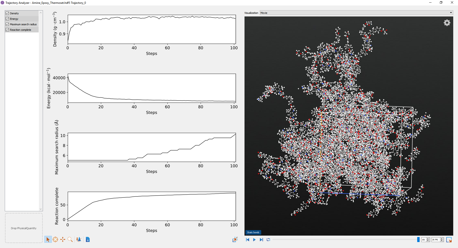
Fig. 21 An example epoxy-amine cross-linking calculation.
It is also possible to see the formation of larger molecular structures when cross-linking by
viewing the trajectory in the Viewer  . Select the trajectory in the Lab Floor and
drag it over to the Viewer. Here you can color atoms in the structure based on the molecule that
they belong to. Molecules are determined by the bond graph of the configuration. In the viewer
plugins open the Color Atoms plugin and set Color by to
. Select the trajectory in the Lab Floor and
drag it over to the Viewer. Here you can color atoms in the structure based on the molecule that
they belong to. Molecules are determined by the bond graph of the configuration. In the viewer
plugins open the Color Atoms plugin and set Color by to Molecules. Also select
Maximize color difference. This calculates the color difference independently for each image so
that it is easier to see each molecule in the image. Select apply and then run the trajectory.
As the trajectory is animated the atoms change color depending on the molecule that they are part
of.
Note
In the trajectory there may be some unreacted molecules remaining at the end of the simulation. This occurs due to the relatively short time used between cross-linking steps. To increase the amount of cross-linking, a larger relaxation time between cross-linking steps can be used. This increases the diffusion of reactive groups between cross-linking steps brings more groups within bonding range. In this system a relaxation time of 50000 steps in both the NVT and NPT cycles leads to the formation of one network structure with no remaining independent molecules.
Using the cross-linking trajectory it is also possible to estimate the gel point of the material.
One method of characterizing this is by estimating the point at which the central sub-structure
grows through the periodic simulation boundaries in each direction. The change in periodicity
in the sub-structure typically leads to a change in its rheology. To calculate the periodicity
of the substructure in each frame of the reaction trajectory, download the provided script
Find_Gel_Point.py. This takes the file name of the trajectory as
an input argument, and plots the resulting periodicity and number of molecules in each frame. A
typical plot from the example system is shown in the figure below. This shows that the system
starts to become periodic at around 64% conversion. This is close to the theoretical gel point
at 58%[4].
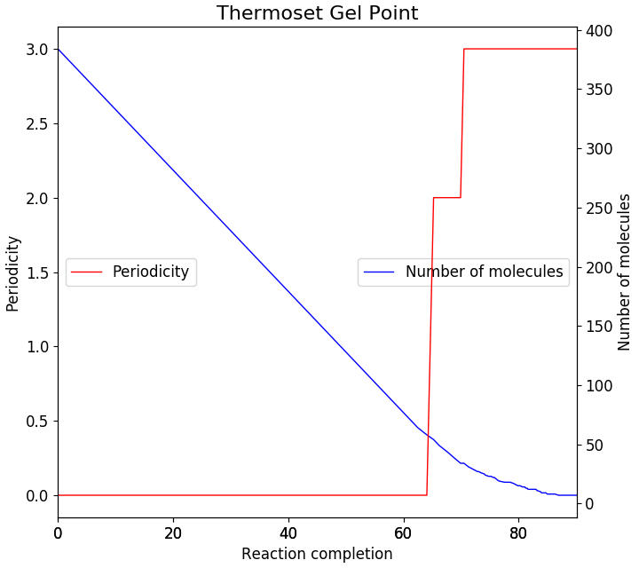
Fig. 22 Estimating the gel point by calculating the periodicity of the molecular sub-structure.
Another means of estimating the gel point is to examine the changing molecular mass of the system
during the reaction. As the reaction starts, individual molecules react together forming larger
molecules. As the gel point is reached these larger structures join together to form one dominant
sub-structures. This can be observed by calculating the average reduced molecular mass of the
system. The reduced molecular mass is simply the molecular mass ignoring the largest molecule.
During the reaction the average reduced molecular mass typically reaches a maximum near the gel
point, as the large individual molecules join the dominant sub-structure[1]. To calculate
the reduced molecular mass, download the attached script
Find_Molecular_Mass.py. As before, this script takes the file
name of the trajectory as an argument, and plots the average total and reduced molecular mass
during the reaction. A typical plot for the example calculation is shown in the figure below. From
this plot it can be seen that the maximum in the reduced mass occurs at 61%, close to the previous
estimates of the gel point.
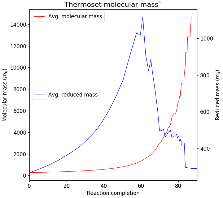
Fig. 23 Estimating the gel point by calculating the average reduced molecular mass.
Conclusions
In this tutorial the process for building a typical epoxy-amine thermoset material was outlined. Using the CrosslinkBuilder tool, a high degree of cross-linking was able to be achieved, although this can be increased by using a longer time step between cross-linking events. Analyzing the reaction process showed that the building process also exhibits a realistic gel point, even at shorter cross-linking intervals. Overall this tutorial shows how reliable models of complex thermoset materials can be easily created in QuantumATK.
References